In this article on variables in atmega32, I’ll describe how to use the AVR Atmega32 Microcontroller’s variables using the assembly code X=(A+B) – (C+D) from Atmel Studio 7. Put the answer from the following equation in the R16 register. Use the simulator to single-step through the program, checking the flags and I/O ports after each instruction has been completed.
We will utilize an arithmetic operation on the variables, but keep in mind that there are registers and variables in the Atmega microcontroller that cannot be used. However, by putting variables in registers, we can define variables.
Moving on to coding and comprehending our program is also important.
Code Explanation of Variables in Avr
Moving on to coding and comprehending our program is also important.
. INCLUDE “M32DEF”
Firstly, we are including a header file.
.DEF X1=R16
Defining Variables in Atmel
.DEF command is used to define any variable. We assigned here R16 to X1. We must store the final result in R16.
.DEF A=R17
.DEF B=R18
.DEF C=R19
.DEF D=R20
.ORG 0X00
.ORG is used as starting location and X represents here hexa values.
LDI A, 0X05
As we already assigned above, Atmega knows that A is R17 in this case.
R17=A=5
LDI B, 0X04
R18=B=4
LDI C, 0X03
R19=C=3
LDI D, 0X02
R20=D=2
We have a question statement to add equations, so we are now adding the variables.
ADD, A, B
Basically, A and B both are registers. It means A=A+B, R17=R17+R18, A=5+4=9
ADD, C, D
Here, C=C+D, R19=R19+R20, C=3+2=5
In the end, we had to subtract the values, so here the result is stored in A.
SUB A, C
A=A-C, R17=R17-R19, A=9-5=4
But our requirement is to store value in X.
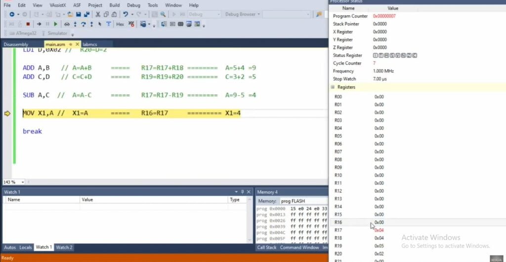
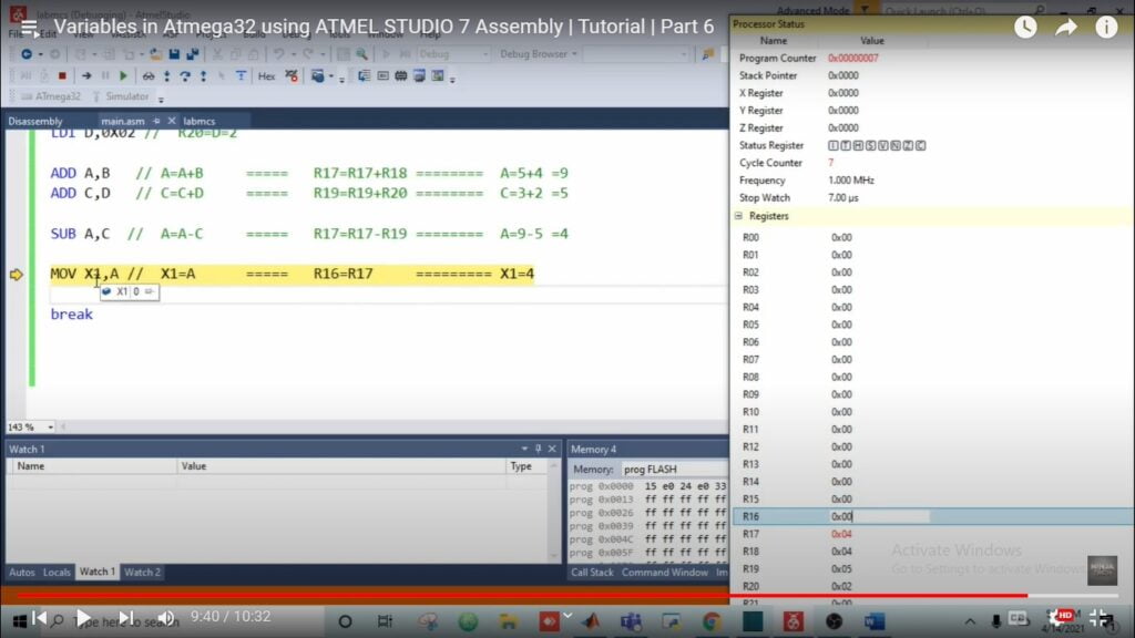
MOV X1, A
X1=A and R16=R17 so, X1=4
We are employing the MOV instruction to save the results in X.
In Depth Explanation of variables in atmega32
Two general-purpose registers have their values changed using the MOV instruction.
The right variable value is substituted for the left one.
break,
When we’re done with our program, we utilize the break command.
Click the F7 key to create a solution, and the F10 key to debug it.
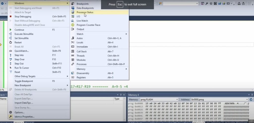
Select the Debug option, then select Windows and select Processor Status.
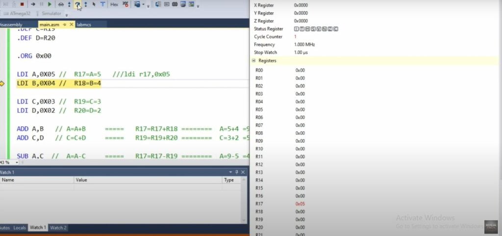
To check the status step by step, click an F10 key, it will step over the code.R17 has an assigned value=5 here.
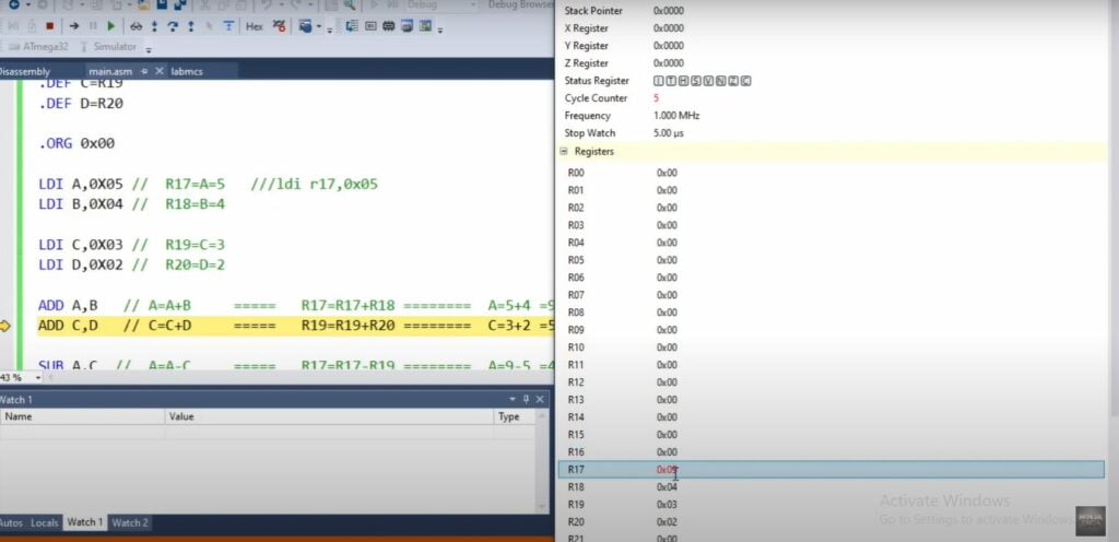
The next step is to add values, R17+R18 both are added, and the result is 9.
When C and D are added, the result is 5.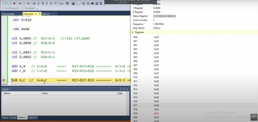
Furthermore, we will now subtract values. The final answer is shown below.
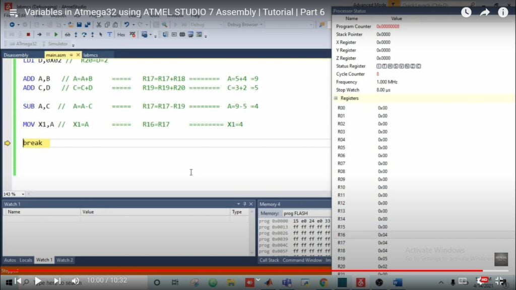
The last step for variables in atmega32 is shown below.
Add instruction works on the general-purpose register, but MOV instruction replaces the values of general-purpose registers.
In R17 the value stored is 4, it should be replaced by R16 and the value of R16 will be 4.
The question may arise in your mind why do we use variables instead of registers, the answer is given below.
Why do we use the variables?
To avoid problems while assigning names to register in a complicated program, we use variables and assign values to them.
Video of Variables in Atmega32
Moreover, If you want to learn about the variables in atmega32 using Atmel studio.
Then, please watch the Video given below
https://www.youtube.com/watch?v=GiH5-16VYTg
Code variables in atmega32
.INCLUDE "M32DEF.INC"
.DEF X1=R16  // X1=R16
.DEF A=R17
.DEF B=R18
.DEF C=R19
.DEF D=R20
.ORG 0x00

LDI A,0X05 //  R17=A=5
LDI B,0X04 //  R18=B=4
LDI C,0X03 //  R19=C=3
LDI D,0X02 //  R20=D=2
ADD A,B   // A=A+B     =====   R17=R17+R18 ========  A=5+4 =9
ADD C,D   // C=C+D     =====   R19=R19+R20 ========  C=3+2 =5
SUB A,C  //  A=A-C     =====   R17=R17-R19 ========  A=9-5 =4
MOV X1,A //  X1=A      =====   R16=R17        ========= X1=4
break
Additionally, If you want to see the project Water Level Indicator Using Atmega32 then visit our website.

