The primary goal of this automatic railway gate controller project is to properly operate and maintain control of the unattended railway gate to prevent accidents at the unmanned railway crossing Furthermore , Accidents are on the rise daily in a nation like ours with so many unmanned railway crossings. These train mishaps are a result of the lack of human labor on the railroad. We have planned to construct the project to prevent mishaps caused by the mentioned difficulty.
Video:
Moreover, If you want to perform Project automatic railway gate controller in atmega32. Then, please watch this Video given below
An innovative circuit that automatically controls the operation of railway gates while sensing the arrival and departure of trains at the gate is known as the Automatic Railway Gate Control System with High-Speed Notifying System.
We can see the train’s arrival and departure thanks to detectors on the railway track that are located far away. The microprocessor that activates the motors that open and closes the railroad gate receives these detectors.
Components of Automatic Railway Gate Controller
The components used in our project are:
- IR OBSTACLE SENSOR
- Atmega32
- L293D Motor driver IC
- Logic Toggle
- 2 Motors
- Ground
- DC generator 12 volt
- VCC 5 volt for sensor
IR OBSTACLE SENSOR
- In this project, the train’s arrival and departure are detected using an IR sensor.
- An IR Transmitter and an IR Receiver are the two basic parts of an IR Sensor. A gadget that generates IR Rays is known as an IR transmitter.
- Like this, an IR receiver is an apparatus that picks up IR rays.
L293D Motor driver IC
- The motor driver IC L293D is utilized in this project to manage the gate motor. A twin H-bridge type motor driver, the L293D Motor Drive IC comes in a 16-pin Dual in-line Package.
- This motor driver IC allows us to operate two motors simultaneously. And then, each of which can move in either the forward or reverse direction.
- High-current consumption devices like DC motors, stepper motors, high-intensity lights, etc. are typically driven by motor drivers. As their input is often a low current signal from a microcontroller and their output is a high current signal to drive the loads, they function as straightforward current amplifiers.
Now, we will move further to see how this project works.
Working of Automatic Railway Gate Controller
A sensor is specifically positioned on a railroad track. In addition, When a train is on the track, the sensor detects an obstruction in its path and closes the gates as the train approaches. Furthermore, Gates won’t open until after a certain amount of time has passed and the train has passed through that section of track.
An obstacle sensor exists that provides data to the Atmega Controller. When the sensor detects a value, it passes the value to the LED driver, which is a motor driver, using the toggle switch. The L293D Motor Driver IC has a dual motor mode. The gate is operated by two motors: one to close it and the other to open it.
Running Railway Gate Controller Project on Proteus
By selecting the Atmega Controller project, you can view your hex file. Since you are also using an infrared sensor, you must also include its hex file. It is simple to download from the internet and save wherever.
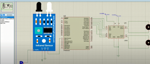
Run the project now. The motors’ LED indicates that our project is operational, as you can see in the image below.
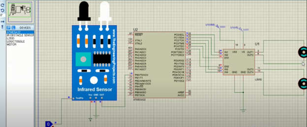
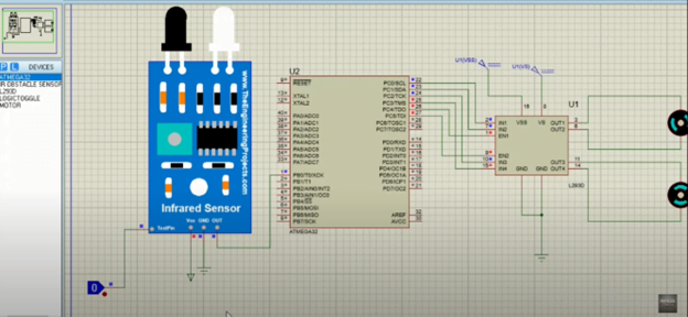
Gates are opened because there isn’t a train on the track yet. When the reading is 1, it implies that the sensor has detected the train’s arrival on the track, at which point the motor will turn on and close the gate. Up till the train does not pass through the track, the motor rotates clockwise.
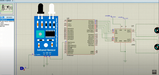
As an illustration,There will be a wait until a certain time, at which point the gates will open. Currently, as you can see, the second motor is operating, signaling that the train has passed and now the door is open. The motor will move in an anticlockwise direction to open the gates.
Advantage
With the aid of this initiative, human labor at level crossings can be eliminated and numerous railroad level crossing disasters can be avoided.
Limitations
- A more effective sensor network can be built into the system to increase implementation efficiency.
- For optimal results, manual wireless control in conjunction with sensor-based control might be employed.
Code:
.INCLUDE "M32DEF.INC"

CBI DDRB,0   // PIN1 CONFIGURED AS INPUT
CBI DDRB,1    // PIN2 //           //

SBI DDRC,0    // PIN1 CONFIGURED AS OUTPUT
SBI DDRC,1     // PIN2   //    //
SBI DDRC,2     // PIN3  CONFIGURED AS //
SBI DDRC,3      // PIN4  //           //

//SBI PINB,0
SBI PORTC,4   ;  pin5 =1
SBI PORTC,5   //  PIN6 OF PORTA AS 1

LOOP1:

 SBIS PINB,0    // SKIP NEXT INST. IF PIN1 OF PORTA HAS 1
 RJMP LOOP1
 SBI PORTC,0   // SET PIN1   //  (1-0)rotating motor1 clock wise
 CBI PORTC,1   // CLEAR PIN2  .. gate closing
 CALL DelayMEGA
 CALL DelayMEGA  // CALLING TIME DELAY FUNCTION

 CBI PORTC,0   // GATE STOP  //CLEAR PIN1
 CBI PORTC,1  // GATE STOP
 CALL DelayMEGA
 RJMP LOOP2

LOOP2:
 SBIC PINB,1     //SKIP NEXT INST IF PIN2 OF PORTA HAS 0
 RJMP LOOP2
 CBI PORTC,2     // CLEAR PIN3   // (0-1)rotatting motor anti clockwise
 SBI PORTC,3     //CLEAR PIN4
 CALL DelayMEGA
 CALL DelayMEGA

 CBI PORTC,2   // GATE STOP  //CLEAR PIN3
 CBI PORTC,3   // GATE STOP  //CLEAR PIN4
 CALL DelayMEGA
 // SET PIN 5   // gate opening
 RJMP LOOP3
LOOP3:
NOP
RJMP LOOP1


 DelayMEGA:                               // function used for delay

ldi     R18,byte3(14* 1000 * 100 / 5)
ldi     R17,high(14* 1000 * 100 / 5)
ldi     R16,low(13* 1000 * 100 / 5)

subi    R16,1
sbci    R17,0
sbci    R18,0
brcc    pc-3

ret
as an illustration I hope you have understood the working of the automatic railway gate controller project. Additionally, If you want to see the project Automatic Car Parking System in Atmega32 then visit our website. Further, If you have any queries, you can comment below. Thanks

