Using Atmel Studio 7 Assembly code, I will explain the CNIC digits to an AVR Microcontroller in this tutorial.
Video
Moreover, If you want to perform and understand CNIC Digits to an AVR Atmega32 Microcontroller. Then, please watch this Video given below
Write and assemble a program to add all the single digits of your CNIC numbers and save
the result in data memory in consecutive location then output this data to Port B.
Explanation of CNIC Digits to an AVR Microcontroller
We will create a program that adds all the single digits in your CNIC numbers and saves the result in a series of locations in the data memory, and then outputs this information. Furthermore, If you don’t want to use your ID number, choose 7 random single-digit numbers.
Use the simulator to single step through the program, checking the flags and I/O ports after each instruction has been completed.
. INCLUDE “M32DEF.INC”
Firstly, we are including here a header file.
.ORG 0x00
.ORG is used for a purpose to give memory a location.
LDI R25, 0XFF
Here R25 is a general-purpose register, in which we have loaded a value, and this value will pass to the data direction register to configure it for output.
OUT DDRC, R25
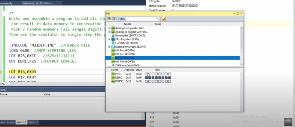
This data direction register is configured for output.
Moreover, instead of taking an Identification Number, we will take any seven consecutive values and will add them.
We will load values in registers R16 to R22.
Loading Register Values:
LDI R16, 0X03
LDI R17, 0X07
LDI R18, 0X08
LDI R19, 0X09
LDI R20, 0X0A
LDI R21, 0X01
LDI R22, 0X50
Adding Register Values
ADD R16, R17
ADD R16, R18
ADD R16, R19
ADD R16, R20
ADD R16, R21
ADD R16, R22
These all instructions will execute, and the result is stored in R16.
STS 0X23, R16
To store values in memory, this instruction is used.
STS command uses two parameters. First, it stores memory address, and second is any general-purpose register, from where we will pick value.
OUT PORTC, R16
The value which was stored in R16 is output on PORTC.
Now, we will build our solution by clicking an F7 key. Moreover, debug the code. Then click on Processor status.
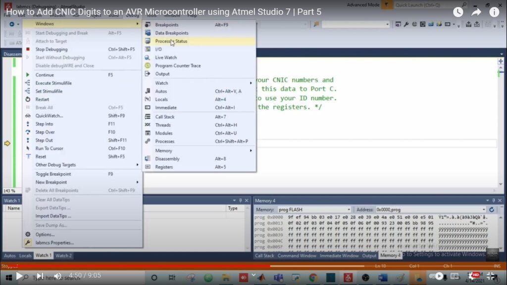
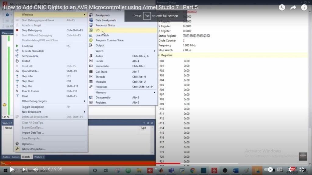
To check your program step by step, click on the F10 key. To see whether our data direction register is configured for output or not, click on the I/O option.
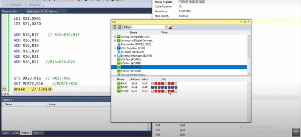
As you can see in the image, our PORTC all bits are 1, which means it is configured for output.
Furthermore, we will check the values now. In R16 value is loaded.
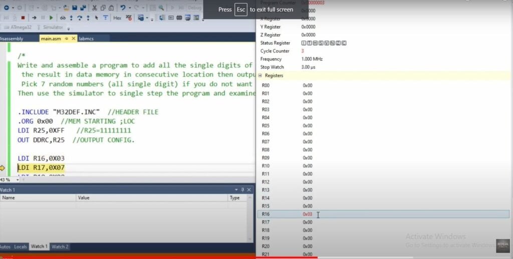
All values are loaded in R16 to R22 data direction registers.
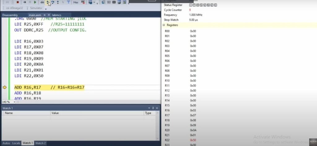
After adding all values, the result will be stored in R16, which is 76.
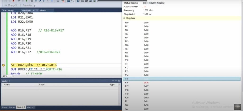
This final value is stored in memory. Now, we will check our value on the output port which is PORTC.
OUTPUT IN PROTEUS CNIC Digits to an AVR Microcontroller
Double-click on Atmega Microcontroller and open your hex file from your saved location. And then run the program.
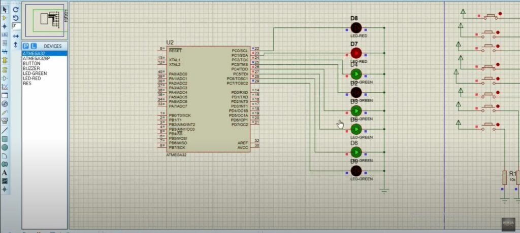
Here also the final answer is 76. The first four LEDs are representing Seven in Decimal. As our LEDs are in binary. So, if we convert it into binary, then seven is equal to 0111. It shows first is 0 so, the LED is off, and the others are 111 so all three LEDs are switched on. The same goes for the other four LEDs.
Code
.INCLUDE "M32DEF.INC"

.ORG 0x00
LDI R25,0XFF
OUT DDRB,R25

LDI R16,0X03
LDI R17,0X07
LDI R18,0X08
LDI R19,0X09
LDI R20,0X0A
LDI R21,0X01
LDI R22,0X50

ADD R16,R17
ADD R16,R18
ADD R16,R19
ADD R16,R20
ADD R16,R21
ADD R16,R22

STS 0X23,R16
OUT PORTB,R16
Break
as an illustration I hope you have understood the working of the CNIC digits in an avr microcontroller. Additionally, If you want to see the project Automatic Car Parking System in Atmega32 then visit our website. Further, If you have any queries, you can comment below. Thanks

