This article will mainly focus on to call a subroutine in atmega32 or a function in atmega32 using ATMEL Studio 7 Assembly. The main function of CALL instruction is to interrupt a program by passing control to external or internal subroutine functions.
Call a subroutine in atmega32
CALL instructions are used to invoke a function or subroutine in AVR microcontrollers. The program counter (PC) is loaded with the address of the subroutine when the CALL instruction is performed, pushing the PC’s current address onto the stack. Upon completion of the procedure, the stored address is popped off the stack and loaded back into the PC using the RET instruction. This enables the application to pick up where it left off in terms of running.
One kind of microcontroller created by Atmel Corporation is the AVR microcontroller and it is frequently employed in many different embedded systems because of its excellent performance and low power consumption.
Let us understand it through a program in assembly language.
Code Explanation
Firstly, we will include a header file.
.INCLUDE “M32DEF.INC”
If you do not know how to include it, you can check by clicking here.
.DEF COUNT=R17 // VARIABLE
Here we assign a variable COUNT as R17 which means wherever we use it that mean it will be equal to the general purpose register R17.
.ORG 0X00
Here we gave the starting location of the program.
LDI R16,HIGH(RAMEND)
OUT SPH, R16
LDI R16,LOW(RAMEND)
OUT SPL,R16 // INITIALIZING THE STACK
To write a program for the subroutine we need to initialize the stack first. High (RAMEND) will be out as a high pointer of the stack and Low (RAMEND) will be out as a low pointer of the stack. It means that we have specified the space for the stack in RAM.
Stack works on the principle of last in first out, which means that when we push the value it goes at the last in the stack, and the last value that we push, pops out first.
LDI COUNT,0 // R17 HAS 0 INITIALLY R17=0
Here we gave the value 0 to the general purpose register R17.
LOOP:
CALL LOOP1 // CALLING SUBROUTINE
RJMP LOOP
.org 0x200
LOOP1: // SUBROUTINE
INC COUNT
OUT PORTB, COUNT
RJMP LOOP
RET
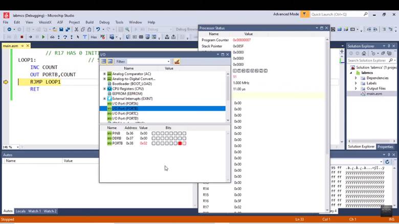
It will first come into the loop and call loop1 which means that whenever we call the subroutine, we use the function of CALL. Then it jumps to LOOP1 and increments the value of the general purpose register. After that we OUT that value on port B and then it will again jump to loop and the cycle goes on. You’ll see the output below.
First of all, build your program by pressing the F7 key.
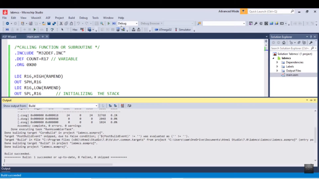
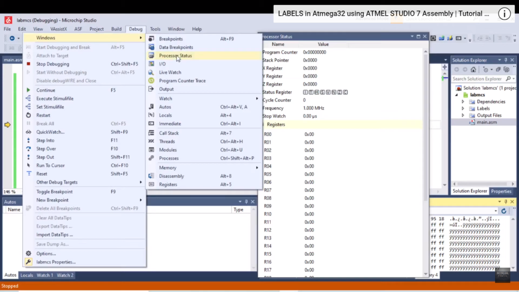
The next step is to debug the program by following the below-given steps.
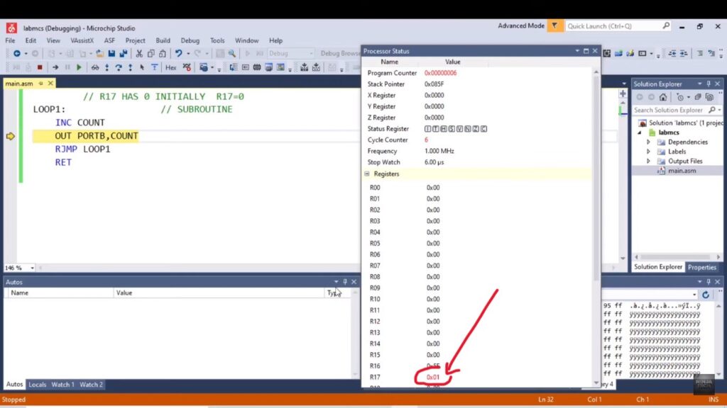
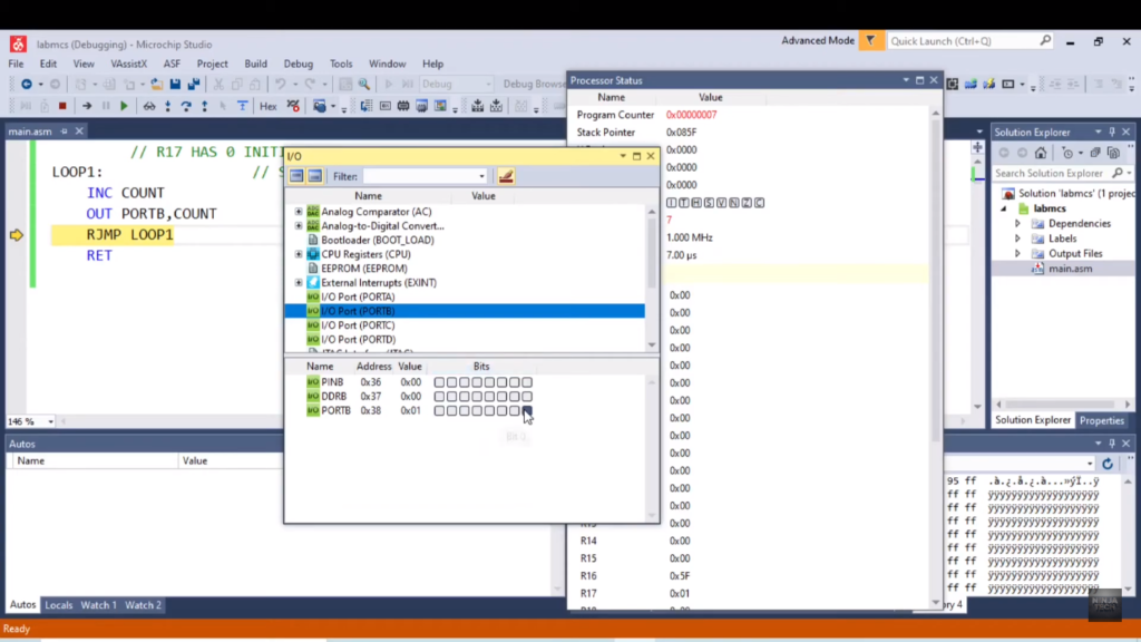
As you can see above port B has the value 1. And after the increment the value has increased.
Conclusion
Code segments that are designated as subroutines are reusable inside a program at any time. The microcontroller pushes a return address on the stack when calling a procedure. After that, it will leap to the subroutine’s location and run the code there. Upon encountering a return statement, the microcontroller will remove the return address from its stack and proceed to the instruction that comes right after the subroutine call.
That’s how you can call a subroutine in atmega32 microcontroller.
The Brief code can be found Below:
CODE:
.INCLUDE "M32DEF.INC"
.DEF COUNT=R17 // VARIABLE
.ORG 0X00
LDI R16,HIGH(RAMEND)
OUT SPH,R16
LDI R16,LOW(RAMEND)
OUT SPL,R16 // INITIALIZING THE STACK
LDI COUNT,0 // R17 HAS 0 INITIALLY R17=0
LOOP:
CALL LOOP1 // CALLING SUBROUTINE
RJMP LOOP
.org 0x200
LOOP1: // SUBROUTINE
INC COUNT
OUT PORTB,COUNT
RJMP LOOP
RET
Additionally, If you want to see the project How to Display CNIC Digits in an AVR then visit our website.

