In this we will see how to create laser security system project. In these days, security alarms are a vital component of many systems. They are intended to identify unlawful behaviors, such as entering a prohibited area or taking a prohibited object or gadget. Different sensors, such as motion sensors, laser light with light sensors, IR sensors, and others, may be used by security alarm systems to provide various indicators.
Video
Moreover, If you want to perform this Project Laser Security System Project then please watch this Video given below
One sort of security alarm system that combines laser light and a light sensor is the laser-based security alarm system. It generally operates by generating a beam of light in a way to justify. If the line of light is broken, the sensor unit detects a change in the output voltage and either trigger an alert or turns on the light.
They are successfully employed for smart monitoring in a variety of structures, including residential units.
In this project, we used the Light Detector Resister in ATMEGA with Atmel Studio to design a Laser Security System Project.
Components used in Laser Security System Project
The components used in the project are:
- Atmega32 microchip
- Torch LDR
- Resistors 10k ohm
- Ground
- LEDs
- DC generator 12 volts for Relay
Working on Laser Security System Project
In this project, a straightforward and efficient laser-based security system is created. Let’s observe how this project operates. We will apply this security system on six walls.
Consider the scenario that we have a house with six walls. Any attempt to approach that wall results in an LED light turning on or an alarm beeping.
LDR (Laser Detecting Resister) will also be used in our project. For security reasons, there will be a resister on the wall. That resister will receive UV rays from LDR that are invisible to the human eye. It will be fixed in a secret location. When someone tries to cross that gap, the rays will strike that individual rather than the resister. Therefore, the buzzer or light will receive a 0 value from the resistor. As a result, the light will turn on or the alarm will sound.
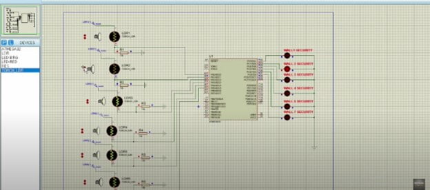
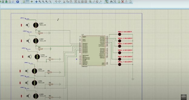
Working on Proteus
We shall now observe how our project on Proteus is operating. LDRs 1 to 6 are the names of the six LDRs. On behalf of each of the six walls, there are also torch LDRs. Additionally, a 10k ohm resister is also included. The light on that wall will turn on whenever anyone tries to approach that private area, alerting the security personnel.
Now, open the hex file in which you have written your assembly language code. Then, click on the run button.
In Depth Explanation
Since there isn’t really anyone to demonstrate the project to, we will intentionally increase the distance between the torch and the LDR. As a result, the LDR won’t get any light from the torch and will instead send a value of zero.
You can see in the illustration below that the LED light will turn on or the alarm will start beeping when the distance between the torch and the LDR is increased against Wall Number 4. In this way, security staff will be informed that someone has entered the house.
Here you can see, the red light is on and the yellow light of LDR is turned off.

The identical outcome will appear if we repeat the process for wall number 2. Here, we can see that because the torch is far from the LDR, the yellow light will send a value of zero, the LED light will turn on, or the alarm will beep, alerting security.
Finally, we will observe that the light will turn off when the torch is removed from the LDR, that is when no one or anything is present.
Advantages of Laser Security System Project
The following are some benefits:
- The Laser Security System has a relatively straightforward circuit, construction, and setup.
- If a battery is added, the laser wall security system can continue to work in the event of a power outage.
Disadvantages of the Laser Security System Project
Some disadvantages of this security system are:
- Only when the laser is deflected does the sensor security system activate. If the attacker walks unaffected by the laser, the attack fails.
- We require more sensors and lasers to protect a greater region.
Applications
In addition to security systems, this laser-based device can be used to confirm whether infants or dogs have crossed a line. This feature adds an extra measure of security, even if the protection locker’s password is cracked.
Code
/*
 Laser and LDR can be used for implementation of security around the boundary walls
 of any organization.
 If the laser light falls on the LDR it gives 1 to the input
pin of the AVR microcontroller otherwise it gives 0 value.
 See the map below,
 there are 6 different walls. Your task is to provide security to all the walls
using Laser and
 LDR connected to different input pins of the AVR microcontroller.
 The system should send the alert to a specific output port incase
of any activity at any wall with its ID.
*/


.INCLUDE "M32DEF.INC"

LDI R16,0X00
OUT DDRA,R16

LDI R16,0XFF
OUT DDRC,R16


WALL1:
CBI PORTC,5

SBIC PINA,0
RJMP WALL2
SBI PORTC,0
CALL DelayMEGA
RJMP WALL1

WALL2:
 CBI PORTC,0
 //CALL DelayMEGA
 SBIC PINA,1
 RJMP WALL3
 SBI PORTC,1
 CALL DelayMEGA
 RJMP WALL2

WALL3:
 CBI PORTC,1

 SBIC PINA,2
 RJMP WALL4
 SBI PORTC,2
 CALL DelayMEGA
 RJMP WALL3

WALL4:
 CBI PORTC,2

 SBIC PINA,3
 RJMP WALL5
 SBI PORTC,3
 CALL DelayMEGA
 RJMP WALL4

WALL5:
 CBI PORTC,3

 SBIC PINA,4
 RJMP WALL6
 SBI PORTC,4
 CALL DelayMEGA
 RJMP WALL5

WALL6:
 CBI PORTC,4

 SBIC PINA,5
 RJMP WALL1
 SBI PORTC,5
 CALL DelayMEGA
 RJMP WALL6


DelayMEGA: // function used for delay
ldi R18,byte3(12* 1000 * 100 / 5)
ldi R17,high(12* 1000 * 100 / 5)
ldi R16,low(12* 1000 * 100 / 5)
subi R16,1
sbci R17,0
sbci R18,0
brcc pc-3
ret
Additionally, If you want to see the project Density Based Traffic Light Control in Atmega32 then visit site.