In this article, I have explained how to Write an assembly program to be downloaded to the Atmel AVR (ATMega16, ATMega32) microcontroller which continuously reads the logic values on port B and writes them to port C.
Let’s get started!
First, make a file. You can see how to make your file using this Video.
How to Blink LED Using Atmel Studio and ATMEGA32 Microcontroller?
This post will help you to make a file step by step.
Components Used For Understanding Port logic in Atmega32
- Button
- Switch Power
- Atmega32 Microcontroller
- LEDs
- Resister
- Ground
Now moving toward our program, you can use any microcontroller of Atmega, I am using Atmega32.
Include the header file of Atmega32 which is .INCLUDE “M32DEF.INC”.
Then we have an R16 register. However, in which we have stored the FF value which means an 8-bit value.
LDI R16, 0XFF // R16== FF==11111111
Now we are outputting the value of R16 in the data direction register. It means that port C is used for configuring output.
OUT DDRC, R16 // PORT C= OUTPUT
Furthermore, we reload a new value in the R16 register which is an 8-bit value. LDI R16,0X00 //R16=00000000
If we give zero value to the data register, it means we are configuring it for input.
OUT DDR, R16 //INPUT=PORTB
Moving further, we are making a loop. Give any name to the loop and end it with any jump instruction.
Again: //: represents loop
IN R17, PINB
IN instruction is used to get data from any special function register to a general-purpose register. Here R17 is general purpose and PINB is a special function register.
R17 receives a value from port PINB and outputs that value to port C.
OUT PORTC, R17 The value from PORTB will be displayed on PORTC.
RJMP Again
Being unconditional, this instruction will continue running indefinitely. It will emit values on PORTC while continually reading values from PORTB.
RJMP can be substituted with JMP, but we chose RJMP because of its efficient operation and tiny memory usage.
Moreover, click on key F7, and it will be built successfully.
Output on Proteus of Port Logic in Atmega32
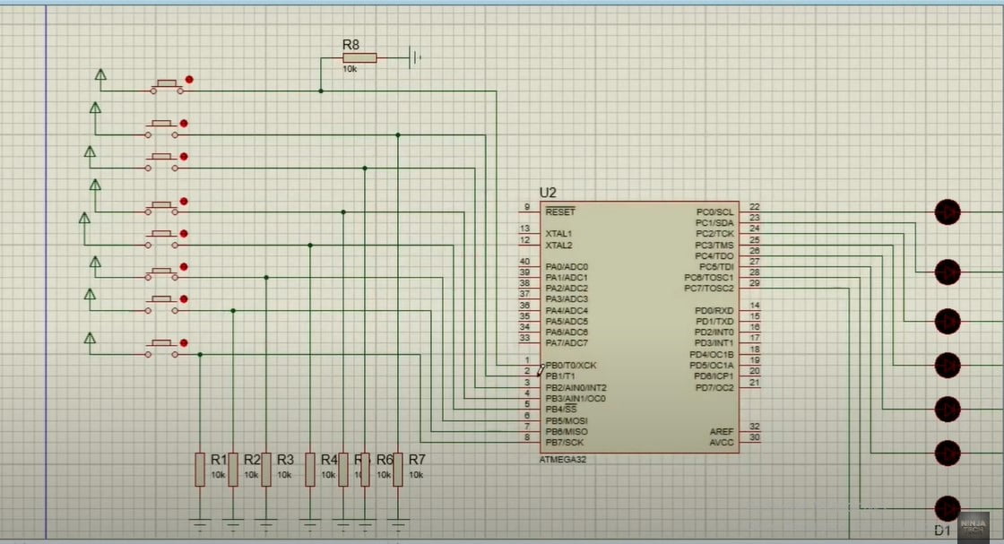
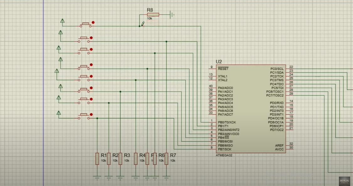
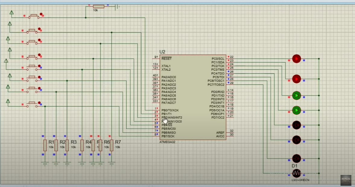
All switches are connected to PORTB, as shown in the image below because PORTB provides value to us. The LEDs are also connected to PORTC. As a result, a 5-volt battery is attached because that device’s voltage is always set to 5. If we are discussing the ground, it indicates that 0 logic is passing, and 1 logic is passing otherwise.
When a toggle switch is pressed, a value of 1 is sent, and when it is not depressed, a resistor linked to the ground sends a value of 0.
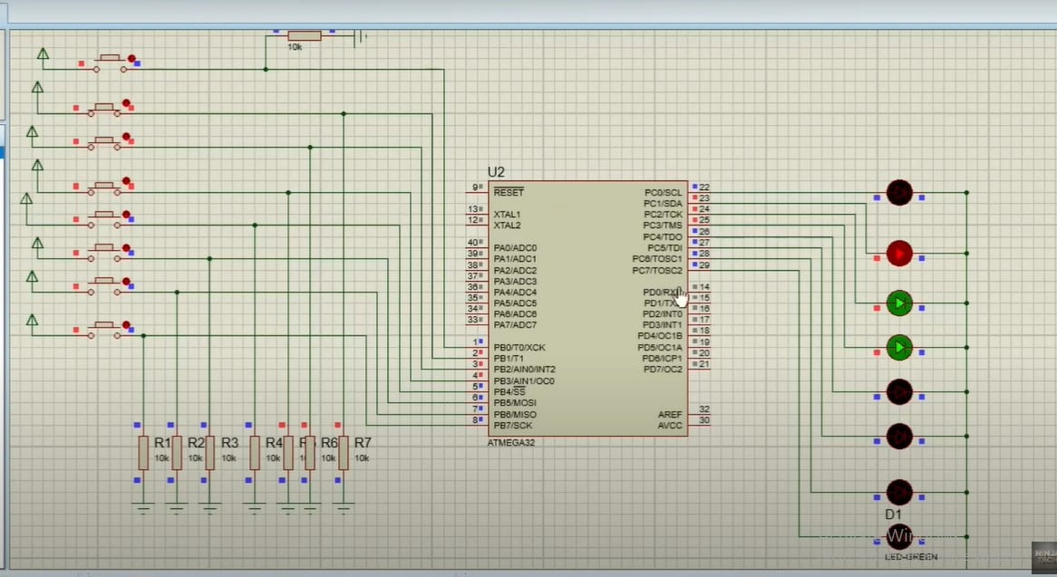
The illustration below shows how pressing a button causes a resistor to advance its value by one value.
With all switches, the same procedure will be done.
Burn the code now by selecting Atmega Microcontroller, opening the file in your Atmel studio, and then opening the hex file.
We shall now evaluate our results. We will first turn off the first four switches then turn on the remaining switches. The other four should pass with a value of 0, whereas the first four should pass with a value of 1.
We will now observe once more that the LED turns off and value 0 passes when we press the first toggle button.
You can repeat the same procedure to check the working of your program.
Video
Moreover, If you want to perform and understand port logic in atmega32. Then, please watch this Video given below
Code
.INCLUDE "M32DEF.INC"

LDI R16,0XFF
OUT DDRC, R16

LDI R16,0X00
OUT DDRB, R16

Again:
  IN R16,PINB
  OUT PORTC,R16
  RJMP Again
as an illustration I hope you have understood the working of the Ports in Atmega32. Additionally, If you want to see the project Automatic Car Parking System in Atmega32 then visit our website. Further, If you have any queries, you can comment below. Thanks


