To identify and indicate the water level in an elevated tank or any other water container, the Simple Water Level Indicator in Atemga32 uses straight forward technology.However, A water level indicator is frequently used in both homes and numerous enterprises. A programmed Microcontroller is a fundamental part of the water level indicator in this project. The amount of water or any other contacting liquid can be indicated with the support of an ATmega32 Microcontroller.
Video:
Moreover, If you want to perform this Project SIMPLE WATER LEVEL INDICATOR in Atmega32 using ATMEL STUDIO & PROTEUS then please watch this Video given below
We can see every level of water contained in a tank or any other vessel with the aid of a toggle switch connected to power. The Microcontroller uses the information from the liquid level sensor (transistor circuit) to determine the amount of liquid currently in the tank by measuring the voltage across the transistor.
In this article, I have explained how the Simple Water Level Indicator in Atemga32 works in proteus. The code is written in Assembly language. We will see the detailed working of the Automated Water Tank in depth.
Features of the Simple Water Level Indicator Project
- Simple installation.
- Easy to maintain.
- A simple yet elegant.
- The automatic water level controller makes sure there are no spills or dry runs of the pump which conserves both water and electricity.
- Energy-efficient, ideal for constant use.
- Avoid leaking from walls and roofs caused by overflowing tanks.
- Completely automated, saving labor.
- Automatic water level controllers provide you the freedom to select the water levels for pump set operations on your own.
- It indicates water levels in the upper reservoir.
Components used in Simple Water Level Indicator Project
1. Transistor 2N3904
A common NPN transistor used as a fundamental electrical device or booster is the 2N3904.Certainly, It can withstand frequencies up to 100 MHz and currents as high as 200 mA when used as an amplifier.
2. Atmega32 Microchip
The AVR improved RISC architecture serves as the foundation for the low-power, 8-bit CMOS ATmega32 Microcontroller. By executing strong instructions in a single clock cycle, the ATmega32 can process strong instructions at a maximum rate of about 1MIPS per MHz
3. Resistors of 10k ohm
A resistor is an electrical device that controls or restricts the quantity of electrical charge which can flow across a circuit in an electronic system. Resistors can deliver specific power to an operational amplifier like a transistor.
4. Toggle switch or Button
It represents a state-changing action. A toggle switch represents two (or possibly more) switchable, mutually exclusive states or possibilities.
5. Motor
6. Relay
Relays are electrical switches that operate by detecting electrical impulses from outside sources to turn on and off circuits. They acquire an electrical signal and communicate it to other components of the system by turning the toggle on and off.
7. DC Generator
Rotating devices known as DC generators can transform mechanical energy into electrical power.
How Does the Circuit for the Simple Water Level Indicator Project Work?
This project’s operation is quite straightforward and is not difficult to comprehend.
There are two primary requirements for our project, “simple water tank level indicator”.
- The water tank is empty.
- The water tank is full.
Let’s talk more about these two conditions.
Working of Simple Water Tank Level Indicator
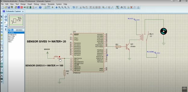
We have two ports Port B and Port C. Make Port B input for the sensor and Port C output for the relay. Whenever the water tank is full (say value 100), the relay must be off and whenever the value goes below the threshold (say 20) relay must be on using AVR Atmega32 Microcontroller.
Explanation:
We will connect a sensor with any pin of Port B, and the sensor will detect the water level in the tank, whether it’s full or empty. Moreover, Port C relates to a relay. Relay acts as a switch when it receives value 1, it attaches its pin with another end, and if it gets value 0, it will go back to its previous position

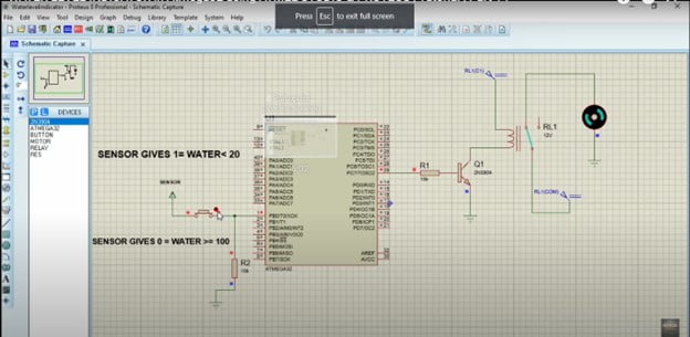
Here, the diagram is shown in Proteus. The toggle Button or Switch is attached to pin 0 of Port B.
The toggle button is up, so, a sensor is sending zero value, which means the Water Tank is Full.
When the Water tank gives a value of less than 20, our toggle button will get on, and the sensor sends a value of 1. Consequently, the value 1 reaches pin 0 of Port B, then, the value 1 at pin 7 of Port C will appear as output here. Furthermore, the transistor is attached to the relay. A relay has 5 pins, 2 of them are connected to power, one is connected to the transistor, and the remaining one is connected to the motor.
As you can see in the diagram, our tank is full, so the motor is off.
Let us discuss now when the water tank is empty.

When a value is less than 20, the switch is on, and the relay pin which is connected to RL1 will connect to another pin to which the motor is connected. So, it will switch on the motor, and it will remain on until our tank is not full.
How Simple Water Level Indicator in Atemga32 works on Proteus?
Double-click on Microcontroller and open the hex file which you have saved in Atmel studio. As our water tank is full and the value is larger than 20, the motor is off when we click the Run icon on the window. Once the toggle switch is turned on, the motor will run until the water tank is not full.
What is the use of Simple Water Tank Level Indicators?
- Hotels, industries, residences, apartments, commercial establishments, drainage systems, and other establishments can employ automatic water level controllers. For single-phase, single-phase underwater, and three-phase motors, it can be fixed.
- Moreover, liquid level indicators are found in large containers in businesses.
Conclusion
A promising microcontroller-based application is the water level indicator. It can be used to measure the levels of another conducting liquid as well.
Code:
.INCLUDE "M32DEF.INC"

 CBI DDRB,0 // PB0 =INPUT
 SBI DDRC,7 // PC7 =OUTPUT

 WATER:

 SBIS PINB,0 // VALUE GOES BELOW 20  RELAY ONN
 JMP WATER1// SKIP IF PB0=SET
 SBI PORTC,7 // RELAY ONN
 CALL DelayMEGA
 JMP WATER

WATER1:
 SBIC PINB,0 // VALUE GOES ABOVE 100
 RJMP WATER
 CBI PORTC,7// PC7=0  RELAY OFF
 CALL DelayMEGA
 RJMP WATER1

DelayMEGA: // function used for delay
ldi R18,byte3(12* 1000 * 100 / 5)
ldi R17,high(12* 1000 * 100 / 5)
ldi R16,low(12* 1000 * 100 / 5)
subi R16,1
sbci R17,0
sbci R18,0
brcc pc-3
ret
Additionally, If you want to see the project How to Blink LED Using Atmel Studio and ATMEGA32 Microcontroller then visit our website.

